Diameter
Defined as the maximum radius of one blade multiplied by 2.
The diameter of the circle scribed by the blade tips as the propeller
rotates.
General rules:
Diameter usually increases as engine power increases and vice versa. (all
other variables remaining constant)
Diameter increases for slower boats and decreases for faster boats.
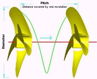
figure 1
Pitch
Theoretical definition:
The linear distance that the propeller would move in one complete
revolution through a solid medium not allowing for slip.
Under actual operating conditions, slip occurs as propellers rotate, so
absolute forward movement (actual pitch) is less than theoretical pitch.
Different types of pitch are:
1. Constant (fixed) pitch - pitch is equal for each radius
2. Progressive pitch - pitch increases along the radial line from Leading Edge to Trailing Edge.
3. Regressive pitch - pitch decreases along the radial line from Leading Edge to Trailing Edge.
4. Variable pitch - pitch is different at selected radii
5. Controllable or Adjustable pitch - blade angle is mechanically varied
Pitch Angle (Not to be confused with pitch!)
Angle of the pressure face along the pitch line with respect to the plane
of rotation measured in degrees.
Pitch angle decreases from the blade root to the tip in order to maintain
constant pitch.
Relationship between Pitch & Pitch Angle
Formula: Tan a = Pitch / 2P r
where: a = pitch angle and r = radius and P=Pi (3.14159)
Pitch Line
A line that passes through the Leading Edge and Trailing Edge of a blade
used as a reference for pitch angle.
Propeller Centre Line (PCL)
Linear reference line passing through hub centre on the axis of propeller
rotation.
Propeller Centre Axis (PCA)
Linear reference line that locates the blade on the hub. Perpendicular to
the Propeller Centre Line (PCL).
Blade Centre Axis (BCA)
Linear reference line that indicates propeller rake.
Blade Centre Line (BCL)
Reference line that intersects each cylindrical section at the midpoint of
the blade section width.
Indicates propeller skew.
Rake
Propeller blade will slant forward or aft from the Blade Centre Axis
(BCA).
Positive rake - blade slants towards aft end of the hub.
Negative rake - blade slants towards forward end of the hub.
Can be specified in inches at the tip or in degrees.
Skew
Blade Centre Line is curvilinear sweeping back from the direction of
rotation. Contour of the blade is not radially symmetrical about blade
centre axis.
Track
Measurement of axial position of all blades with respect to each other.
Rotation
Right hand propeller rotates clockwise when viewed from astern facing
forward.
Left hand propeller rotates counter clockwise when viewed astern facing
forward.
Twin screw applications utilize both LH (port side) and RH (starboard
side) rotating propellers.
Blade Numbering
By convention the blade located at the position of the keyway is
identified as Blade 1, the next blade in rotation is Blade2 and so on.
Blade Sections
Referred to as Cylindrical Sections.
Hub & fillet area account for about the first 20-30% of the sections.
Blade Section Length & Stations
Section length is the same as blade width.
Each station is expressed as a percent of radius increment ( eg 40 radius
is 40% of the blade radius) .
Blade Section Types
Naca: Symmetrical section. When performance is equal going astern or
ahead.
B.Troost: The most commercially used hydrodynamic profile (airfoil).
Ogival: Used when pressure-cavitation conditions are higher, this section
withstands more pressure before cavitation reaches 3-4%, but is less efficient
than B.Troost.
Hybrid: By combining both the B.Troost and Ogival, this hybrid maximizes the
benefits of both sections.
Airfoil section - resemble traditional airplane wing sections -
i.e. rounded Leading Edge, maximum thickness at about 1/3 length of blade
aft of the Leading Edge.
Supercavitating section - high speed application Sharp Leading
Edge, maximum thickness near Trailing Edge.
Blade Thickness
A blade is thickest at the root for structural integrity.
Within each radial section, the point of maximum thickness may not
necessarily coincide with the midpoint of the chord length.
Blade Thickness Fraction (BTF)
Maximum blade design thickness as extended to the propeller centre line /
propeller diameter. Blades must have enough thickness to achieve desired
sectional shape and provide sufficient strength under loading. Blades that
are too thick produce less propeller efficiency.
Disc Area
Area of the circle scribed by propeller blade tips (P r˛) where P=Pi
(3.14159) and r = radius (1/2
diameter) of the propeller.
Projected Area Ratio (PAR)
Area of projected outline of propeller divided by disc area.
Smallest area ratio.
Developed Area Ratio (DAR)
Similar to Projected Area Ratio if pitch were 0.
Area of blade rotated to 0 pitch divided by disc area.
Most widely used area ratio reference.
Expanded Area Ratio (EAR)
Similar to Developed Area Ratio with sections "unwrapped" from hub.
Largest area ratio.
Camber
Defined as curvature in the mean thickness line of the blade section. Blade Tip
Maximum reach of the blade from the centre of the hub.
Separates the leading and trailing edges.
Leading Edge (LE)
Edge of the blade that first cuts the water.
Trailing Edge (TE)
Edge from which the water exits the blade.
Blade Face (Pressure Side or Pitch Side)
Side of the blade facing toward you while viewing from the vessel’s stern.
Blade Back (Suction Side)
Side of the blade facing away from you while viewing from the vessel’s
stern. Blade
Root (Fillet area)
The area where the blade attaches to the hub.
Hub
Solid cylinder located at the centre of the propeller.
Bored to accommodate the engine shaft.
Hub shapes include cylindrical, conical, radius, & barrelled.
Keyway
Slender rectangular slot broached into the interior of the hub.
Helps to secure propeller to the shaft and prevent rotational slipping on
the shaft. Cup
Small radius or curvature located at the trailing edge of blade.
Cupping, helps to reduce or delay cavitation.
Helps to reduce slip, thus increasing actual pitch and usable thrust.
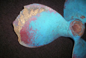
Cavitation
Cavitation
Cavitation is the phenomenon of water vaporizing or boiling due to the
extreme decrease in pressure on the forward, or, suction side of the
propeller blade. Cavitation can be caused by nicks in the leading edge,
bent blades, too much cup, sharp corners at the leading edge, incorrect
matching of propeller style to the vessel and engine or, simply high
vessel speed.
Ventilation
Sometimes the term cavitation is used when in reality ventilation is
actually occurring. Ventilation is air from the water surface or exhaust
gases being drawn into the propeller blades which causes the propeller to
over rev and lose thrust. This is the effect that you sometimes feel when
you are running in a following sea in rough weather.
Singing
Some propellers in service produce a high-pitched noise, often referred to
as Singing. This sound typically is a clear harmonic tone much like a
humming or ringing wine glass.
More of an annoyance than anything harmful, the causes of singing are
not completely understood. Many theories have been put forward to
account for the phenomenon of Singing, but it appears to be affected by
critical factors for which the theories make no allowance. For example a
twin-screw vessel has one propeller that sings and the noise is
eliminated just by switching position of propellers. Or a singing
propeller is replaced by an identical spare Propellers which is found to
be silent. Also the lower the number of blades on a prop the less
chances of "singing".
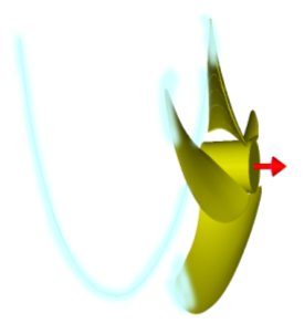
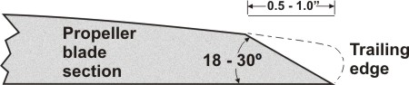
Anti-singing Edge
The singing is a result of propeller diameter and R .P.M. , Boat speed
and Trailing-edge thickness and shape or roundness. In most of the cases
not much can be done on Diameter, Rpm's or speed, but we can modify the
Edge Geometry. This has been the Strategy for all efforts to eliminate
singing.
Most Propeller professionals (and others) are familiar with the
Anti-singing Edge – a Chamfering of the Trailing edge, typically on the
Suction side. This shape avoids the creation of curving flow eddies by
cleanly separating the water flow off the blade.
The following graphic shows the Chamfering that goes from 0.5 or 0.4
Radius to the tip of Suction Side.
However the adoption of unduly thin edges can result in erosion or
fracture of the blade near the edges. Anti-sing Edge may be considered
as a last resort to minimize the Singing of an existing Propeller.
Slip
The difference between the theoretical distance the propeller should
travel in one revolution and the actual distance the vessel travels.
For example if you cruise at 2000 rpm and your vessel has a 2:1 reduction
gear, a wheel with 24" pitch, your theoretical speed through the water
should be 19.74 knots (the distance a 24" wheel should move in one hour).
In reality your vessel only does 14 knots at 2000 rpm on a calm day with
no current, the difference is slip.
Article: Propeller Sizing - Have you got the correct propeller?
|