OLDS ENGINEERING Marine Division |
|
|
|
|
|
Maximizing Propulsion EfficiencyAre there gains to be made by new technology?By David Barringhaus and Robert Olds - Olds Engineering � Marine Division - Maryborough Qld Aust.
BACKGROUND
Since that time, the art and science of marine propulsion has steadily advanced through better understanding, resulting in better design, performance and efficiency. Through the advent of computer technology, more precise designs can be achieved.
GAINING AN UNDERSTANDING INTO EFFICIENCYOf all the food primary producing methods in the world today, fishing continues to be the most energy intensive due to its high dependency on internal combustion engines (Wilson,J.D.K 1999). A New Zealand study prioritized what were the major causes of fuel inefficiency. In order of priority: - People - principally the vessel
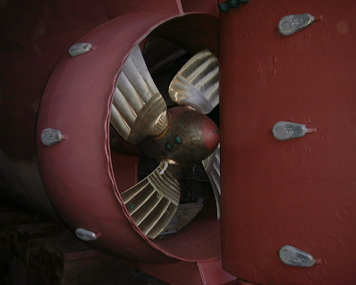
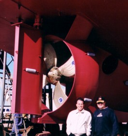
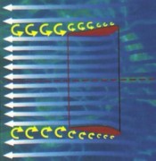
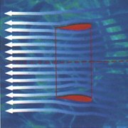
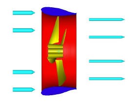
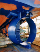
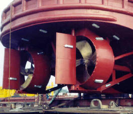
operator To this we add: - Running open propellers when a nozzle will save 22% fuel or more on most trawlers, fishing and tuna vessels up to 15 knots. HOW PROPELLERS WORK - The High / Low Pressures of PropulsionLet us freeze a propeller in motion. With right hand rotation, the propeller blades will rotate clockwise viewed from behind. As the blades push down, water is forced down and back, as is done by your hand when swimming. Because this motion has created a space, water must rush back simultaneously to fill the void resulting in a pressure difference between the two sides of the blade. There is a positive pressure or pushing effect on the driving face of the blade, and a negative pressure or pulling effect on the front face of the blade. As the propeller rotates, it draws water from its front through an imaginary tapered cylinder a little larger than the propeller diameter at the front. As the water passes through this imaginary cylinder, the water accelerates as it passes through the narrower end of the cylinder. This acceleration of water results in the force that we know as thrust. HOW A NOZZLE WORKSTo obtain the most thrust, a propeller must move as much water as possible in a given time. A nozzle will assist the propeller in doing this, especially when a high thrust is needed at a low ship speed. As we already know, as the propeller blades rotate in the water, they generate high-pressure areas behind the each blade and low pressure areas in front, and it is this pressure differential that provides the force to drive the vessel. However, losses occur at the tip of each blade as water escapes from the high pressure side of the blade to the low pressure side, resulting in little benefit in terms of pushing the vessel forward. The presence of a close fitting duct around the propeller reduces these loses by restricting water flow to the propeller tips.
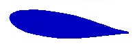
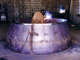
The section of a Rice-Speed Nozzle was developed from air wing sections displaying highest lift/lowest drag properties. When nozzle sections of Kort 19-A and Rice-Speed are compared in Figure 2 below, the drag coefficient of a Rice-Speed Nozzle is 17 times lower than Kort 19-A type.
OPERATIONAL ANALYSIS OF A RICE SPEED NOZZLE
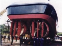
CONCLUSIVE TESTSTo demonstrate the difference in design efficiencies, a test was conducted using the following: - Three 72 foot trawlers of 375 Hp One was fitted with an open propeller, one with a Kort nozzle and a kaplan propeller, and the third with a Rice Speed Nozzle and Ka speed propeller. The results tabled below in Table 1
The significance of these results is in the: Putting it simply - More thrust, More Pulling Power, More Speed, from the same power input, for less fuel. Independent trawler operators in Australia, have achieved greater than 25% fuel saving using a Rice nozzle system compared with their previous open propeller. Also, each recorded a speed gain of around 0.5 to 1.5 knots. Tuna longliners have reported an extra 1 knot coupled with fuel savings as a result of fitting the Rice speed nozzle system.
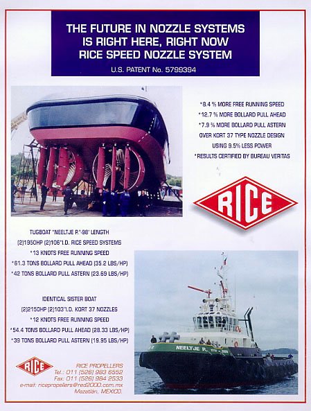
It has also being reported in the Canadian Dept. Agriculture and Fisheries newsletter, that the Jenny Mae Fisheries in Nova Scotia have gained 2000lbs more towing power and extra travelling speed by the use of a Rice Speed Nozzle. A Rice Speed Nozzle and propeller were retrofitted to two of their vessels with all of their vessels to have the same systems installed in due course. It also should be noted that due to the effectiveness of the new system and reduced fuel costs, the Canadian Government cost-shared in the installation. Ultimately, the application of Rice Propulsion Systems would be further enhanced by better vessel design that would incorporate reduced water disturbance around the propeller aperture. We would encourage boat designers and Naval Architects to consider this system when designing their vessels not only for the fishing industry but also cruising vessels to 15 knots. In a further trial (Table 2) with the results certified by Bureau Veritas, between two sister tug vessels, the Rice Thrust Nozzle System again outperformed the older Kort 37 nozzle. Table 2. Trail Conducted Between Two Sister Tug Vessels. (Results Certified by Bureau Veritas)
PROPELLER DESIGN
Apart from the engine that supplies the energy, the propeller is the most important single item on your vessel. Its design and specifications directly affects the propulsion efficiency, and therefore fuel costs. Marine propulsion has close relationships with the aeronautical and hydrodynamics fields of study. While there are theoretical designs that can be produced, it has been left to companies like Rice to advance the designs through consultation with NASA and the end users of their product. There are a number of crucial factors in a propeller's design that affect its efficiency. To ascertain if the correct propeller is fitted on a vessel, a few simple questions can be asked. They are:
- Does the engine rev beyond designed RPM at full throttle and is
underloaded? The importance of these factors differs depending on application. We will address those that are relevant to the fishing/trawling type vessel. Diameter
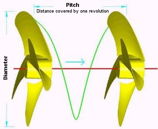
Although vessel design plays a part in propeller diameter, the RPM and power being delivered to the propeller primarily determine it. Diameter is the single most critical factor in determining the amount of power a propeller can absorb and transmit. Therefore, it is the most important single factor in determining the amount of thrust delivered. General rule of thumb is the slower operating speed of the vessel, the larger the diameter. As the propeller RPM decreases through engine speed and/or gearbox reduction the diameter should increase. The diameter of a given propeller should be stamped on the hub. The markings should have at least two sets of numbers separated by a 'x'. The first set of figures relate to the diameter, the second set, the pitch. Mostly, the figures represent inches. DARDeveloped Area Ratio or BAR: Blade Area Ratio. Is the area that blades cover on the total circle area of propeller diameter. The Dar and the diameter are the power transmitters. Pitch
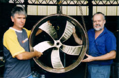
Pitch is the distance that the propeller would move in one (Figure 1) revolution, like a nut along a bolt. The pitch is usually stamped on the hub of the propeller. For example, the markings may read 61(the diameter) x 59(the pitch). This means that in theory, the propeller would move forward 59 inches in one rotation. General rule is, the higher the RPM, the higher the pitch. Too lower pitch will cause the engine to race causing excess stress and fuel consumption. Signs of to lower pitch are increased acceleration, poor top speed. Too higher pitch will result in reduced engine RPM and torque. Signs are poor acceleration, poor pulling power. Top end speed may not suffer much. Blade NumberWhy select 3, 4, 5 or more blades? The lower number of blades the more efficient the propeller. The ideal number of blades would be 1; nothing would disturb the incoming water flow. For manufacturing purposes the most convenient is 3 blades, but for area and balance it is 4 or 5 or more. With more blades, the loading pressures are more evenly distributed and the vibration possibilities reduced. Five blade propellers are extremely smooth. A three blade propeller with the correct DAR will be more efficient than a five blade with a similar DAR. RakeBlades lean or slope either forward or aft viewed from the side: the distance or angle is called rake and is used to place greater diameters in reduced spaces. Greater rake of a propeller blade, has more importance to surface piercing propellers, and will not be addressed here.
Blade Section ShapesNaca: Symmetrical section. When performance is equal going astern or ahead. B.Troost: The most commercially used hydrodynamic profile (airfoil). Ogival: Used when pressure-cavitation conditions are higher, this section withstands more pressure before cavitation reaches 3-4%, but is less efficient than B.Troost. Hybrid: By combining both the B.Troost and Ogival, this hybrid maximizes the benefits of both sections. Cavitation
The boiling point of water at sea level is 100 degrees C. But when the atmospheric pressure drops, so does the boiling point of the water. We already know that as propeller moves through the water the pressure at the front of the blade is lowered. This also can be said for the leading tips of the propeller blades. As the speed of the propeller increases, the pressures are reduced, causing the water to boil forming water vapour. As the water vapour bubbles role across the blade into higher pressure areas that will not support boiling, they collapse back into water. The collapsing action of the water vapour generates energy that erodes away the blades, causing cavitation. Cavitation can be associated with low fuel consumption, as the propeller is unable to absorb the power of the engine, and the engine runs underloaded (Wilson.J. 1999). Causes of low pressure areas of a propeller can be too sharp a leading edge, nicks, or poor propeller design. It is of utmost importance the propeller be maintained in a good clean condition. Propeller MaintenanceIt is important to maintain the propeller in good condition. The U.S. Navy has reported that 7 months of marine growth on a propeller, causes up to 10% greater fuel usage to maintain the same ship speed. By keeping just the propeller alone in good condition has a big payback for little expense. SKEWED PROPELLERS
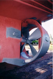
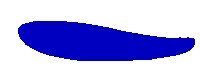
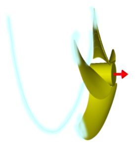
In addition to searching for a lower advance resistance nozzle profile that would demand lower engine power, the advantages of a skewed propeller design were added to those of a regular propeller, resulting in the Skewed Kaplan design which provides a higher performance. In the 60's skewed propellers started to be used on submarines to obtain a silent and vibration free performance. In the 70's, they were used on cruisers and very expensive yachts - all searching for the same benefits. In the 90's we applied these skewed propellers benefits to working vessels. The advantages provided by skewed propellers compared to those of regular design are now known worldwide : - Reduction of level forces excitation.
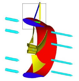
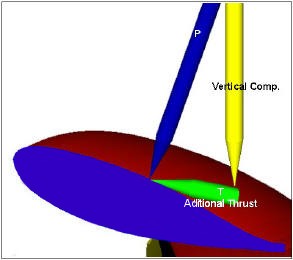
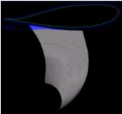
As nozzle manufacturers Rice decreased roundness tolerances, allowing us to also reduce propeller tip clearance from 0.8% of propeller diameter to 0.6%. This increased the overall efficiency of propeller-nozzle unit. In order to maintain a constant propeller tip clearance on the curved inside section of the nozzle, we increased propeller diameter on trailing edge of the blade tip section - as indicated in blue. CONCLUSIONThe efficient hydrodynamic shape of the Rice Speed Nozzle makes the water flow faster and easier through and around the foil section of the Rice Nozzle than the older Kort design. More propulsion is achieved for the same power input because a propeller with a much greater pitch is possible. The nozzle helps to improve the propeller itself. In addition to the propeller's efficiency, the nozzle itself generates driving forces in a similar way to the lift produced by the wing of an aeroplane. Are there gains to be made by new technology? We believe there are through Rice Technology. BiographyBoth Robert Olds and David Barringhaus are working shareholders of Olds
Engineering with Robert being the Assistant Manager. They are both members of
the Marine Division. Robert and David are very much hands on in their
positions with some 40 years experience between them. Reference: J.D.K. Wilson - Food and Agriculture Organization paper Fuel and Financial Savings of Small Fishing Vessels - 1999)
Wm. Olds & Sons Pty. Ltd. trading as OLDS ENGINEERING |
||||||||||||||||||||||||||||||||||||||||||||||||||||||||||||||||||||||